News
05.08.2024
Fixing air quality in and around steel mills is easier than you think
Computer simulations of flow-dynamics have enabled incredible leaps in technology that are yet to be utilized in our aging steel plants.
05.08.2024
Computer simulations of flow-dynamics have enabled incredible leaps in technology that are yet to be utilized in our aging steel plants.
Computer simulations of flow-dynamics have enabled incredible leaps in technology that are yet to be utilized in our aging steel plants.
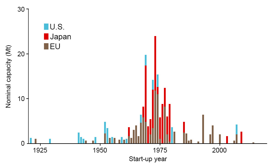
A large portion of the steel production capacity in places like Europe, the United States and Japan was built around the mid-1970’s and even earlier. The dust extraction systems of these plants were mostly designed at the time of construction and only few have undergone significant upgrades. At the time, we simply did not know very much about the severity of PM2.5 and other microparticles’ impacts on human health.
The following graphic is adapted from a research publication on the age structure of globally operational blast furnace equipment.
Our scientific understanding of flow-dynamics has skyrocketed in recent decades mainly due to effective computer simulations. Unfortunately, this progress is barely visible in the steel mills of today.
A common misconception is that improving air quality in and around steel plants would require replacing the very expensive main filtration system – an apartment-building-sized baghouse unit in most cases.
The good news is that there are a number of low-hanging fruit when it comes to effective and inexpensive solutions to the dust problem.
An overwhelming proportion of the dust is generated in a few, very specific places in the steel-making process. The production capacities of these sites have also increased over the years, outgrowing their respective dust control systems. Simply improving the local ventilation systems and increasing capacity at the problem areas with modular units makes an enormous difference.
Hot, dust containing gasses are formed during:
Combustion-related particulates can be reduced mainly by monitoring and improving the combustion efficiency of the process.
The steam-like expanding gasses from rapid vaporization and chemical reactions must in turn be contained by a voluminous enough exhaust hood, and not allowed to spread freely into the facility.
Dry dust from handling scrap metal, slag and raw materials like iron ore, coal and limestone, escapes during:
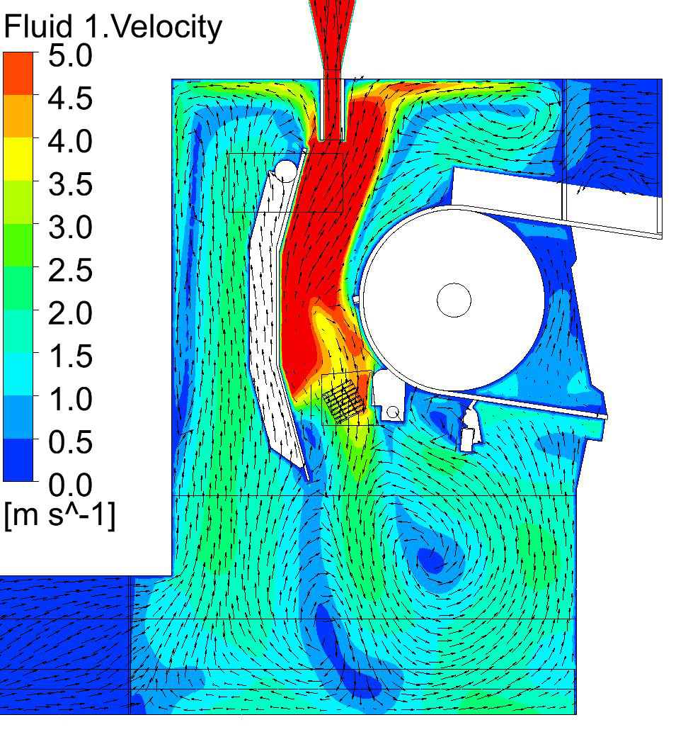
Properly capturing the dust at the primary source in these problem areas is essential to the solution. Fortunately, the emergence of Computational Fluid Dynamics (CFD), has resulted in much more efficient hooding and ducting designs. The following example shows an encapsulated conveyor transfer point with a closed loop solution.
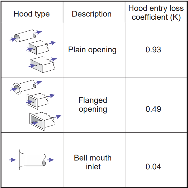
Below is another excellent example from the dust control handbook of CDC’s National Institute for Occupational Health and Safety, illustrating how much of an effect small changes in design can have.
Conveyor belts, and particularly their transfer points, are a common problem area, where fugitive dust can be minimized by fixing simple issues like:
Other important and easy fixes have to do with controlling the airflow around the transfer points:
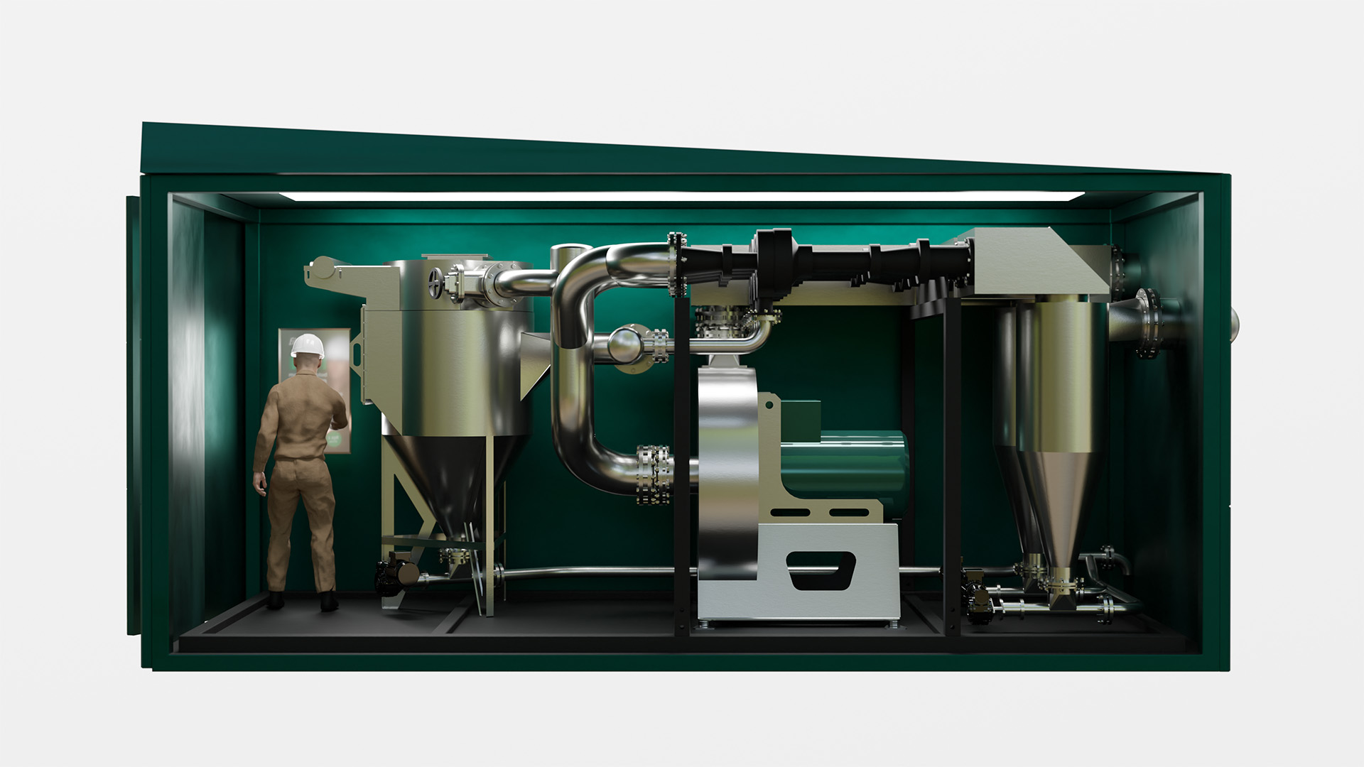
Computer simulations have also enabled the emergence of technologies like the flow-dynamic filter, that function on a continuous basis in modular units that can be placed at the dust-generating site, reducing the load on the main filtration system.
Earlier is better
The impact of removing dust particles from material is multiplied over each link in the chain of moving the material towards its final destination in the facility.
One such critical end point is the charging of the blast furnace or EAF, where conditions are difficult for containing dust. Introducing an opening to the furnace in order to feed the material creates a powerful outward current as the heat escapes the furnace, which then spreads the dust around in an uncontrolled manner. It’s essential that any material reaching this stage is as dust-free as possible.
Special attention should be paid already at the point of unloading the material from a ship or train. Any small particles removed at this stage are particles that can’t escape in the next vulnerable junctions.
The latest evolution in dust control involves placing a modular unit at the point of unloading, where material with characteristics suitable for the method, is first fed into a conveyor. This unit creates a closed loop system, which utilizes a push-pull mechanism of airflow by generating suction at the top of the hood while simultaneously pushing the cleaned air back underneath the enclosed conveyor transfer point. The aim is to create an intentional disturbance in a controlled environment, where as many small particles as possible separate from the mass and can be recovered.
The benefits of fixing the dust problem and reducing the PM2.5 and PM10 emissions are on one hand obvious and well understood:
And on the other hand less well known:
Capturing and reusing the dust represents a direct reduction of virgin resources that need to be mined, transported and processed, resulting in lowered CO2 emissions as well.
Particularly much high-value dust is produced in the coking plants of Basic Oxygen Furnace (BOF) steel plants, and in the furnaces of Electric Arc Furnace (EAF) type steel plants.
The dust is also very abrasive and affects every piece of machinery in the plant. Lubricating oils turn into sludge and metal parts wear down faster because of it.
With modular units like the flow-dynamic filter, the maintenance needs of the main dust filtration system itself are also significantly reduced, as most of the abrasive dust is removed at the point of origin.
The investment required to fix the dust control problem is not nearly as large as one might expect. Improvements to the hooding, ducting and conveying are extremely affordable and more a matter of taking action. Modular units like the flow-dynamic filter can also be leased rather than owned, and don’t require building permits.
To learn more about the flow-dynamic filter, please visit the Technology page of our website and our product brochure.
![]()